Introduction
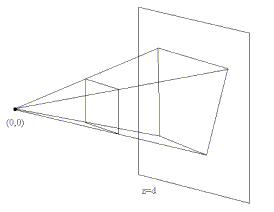
In this session we will project 3D figures onto a 2D plane (like a computer screen). Given a number of points with coordinates (x,y,z), the goal is to determine the corresponding point with coordinates (x',y') in the 2D plane, based on a perspective projection.

We can project a point p on the plane z=d by drawing an imaginary line from a viewpoint through the point p and then calculating the intersection point of this line with the plane. Projecting a polygon boils down to projecting its vertices and connecting the projected vertices in the same way as the original vertices.
You can use the following source code as the skeleton code for this session.
Exercises
Exercise 1: projecting 3D coordinates onto the plane
Given a viewpoint p0 with coordinates (x0, y0, z0) and a point p1 = (x1,y1,z1), calculate the projection of this point onto the plane z = d where d is a constant (a real number). You can calculate the x and y coordinates of this point by means of the parametric equation of a line through p0 and p1. This gives you a system of 3 equations that can be easily solved by means of the additional equation z = d.
Once you end up with an equation that expresses the x and y coordinates in terms of p0, p1 and d, you can implement the equation in the code. Add your implementation to the project method of class 3DPoint and in the draw method of class Polygon. The draw method has the following signature:
void draw(Point3D eye, double zoom)
eye signifies the 3D coordinates of the viewpoint p0. The 3D coordinates of the points to project (p1, ...) are stored in the vertices array of the Polygon class. zoom is the constant d determining the depth of the projection plane.
When drawing a 3D object, one issue to take into account is the mapping of the 3D coordinates onto actual screen coordinates (i.e. pixels). The coordinates of models in your 3D world are expressed relative to the origin (0,0,0). When projecting onto the plane z = d, the points to draw are points (x,y,d). However, these x and y coordinates are still relative to the origin. You will need to map them to screen coordinates (via scaling and translation), such that the point (0,0) corresponds to the middle of the screen (width/2, height/2).
Once you finished this exercise, you can test whether your projection code works by constructing a wireframe 3D model and drawing it. Constructing such a model is the topic of the next exercise.
Exercise 2: Perspective Projection of a Cube
Use your algorithm from exercise 1 to project a 3D cube onto the screen. A cube consists of 8 corner vertices and 6 planes. Construct a cube with edges of length 1 (in the 3D model) and with one of the corner vertices being (0,0,0).
In the code, we represent the cube as an array of 6 Polygon objects. A Polygon object in turn encapsulates 4 3D coordinates that together represent one side of the cube.
Exercise 3: Rotation
There are two ways to make the cube rotate on the screen: either you rotate the cube (i.e. the coordinates of its corner vertices) or you rotate the viewpoint (the camera). We will implement rotation by means of the first manner (rotating the cube itself).
Rotation in 3D is very similar to rotation in 2D. To keep things simple, we will not consider general rotations around an arbitrary axis, but only rotations around the X, Y and Z-axes. Such rotations can be described in terms of the following matrix transformations:
 |
||
 |
||
 |
A point represented as a vector [x,y,z]T can be rotated by multiplying it with one of the above rotation matrices. Implement rotation in the rotate methods of the Point3D class. A Polygon can then be rotated by rotating all of its vertices, and a Figure by rotating all of its Polygon sides.
If your implementation is correct, you should see your cube rotating along the X and Y axes by means of the arrow keys and in the Z direction by means of the page up and page down keys.
Exercise 4: Perspective Projection of a tetrahedron
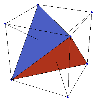
Construct a tetrahedron wireframe. A tetrahedron consists of 4 corner vertices and 4 triangles. You can derive their coordinates by means of the following example figure:

In the code, we represent a tetrahedron as a Figure of 4 Polygon objects, where each Polygon represents a triangle and thus has 3 vertices.
Exercise 5: Scaling
Make sure you can zoom in and out of your cube or tetrahedron. Again, there are two ways to scale a 3D model: scaling the coordinates of the model itself (zooming in = dividing by a factor, zooming out = multiplying by a factor) or manipulating the viewpoint (the camera). Implement scaling, this time by manipulating the camera. One easy way to scale a figure is by moving the projection plane (closer or farther away from the viewpoint). You can test the code by means of the '+' and '-' keys.
Exercise 6: Translation
Again there are two ways to translate a model: translating the model coordinates or translating the camera. Implement translation by translating the model coordinates. To do so, implement the translate method of class Point3D. You can test your code on the cube or tetrahedron by means of the keypad keys 2 and 8 (Y direction), 4 and 6 (X direction) or 0 and 5 (Z direction).
Exercise 7 (optional): Z-buffering
Try to use your algorithms of the previous session to colour the projected sides of your cube or tetrahedron, or to map textures on them. You will notice that colouring the planes is easy, but the order in which they are drawn may not always be correct. There are multiple ways of dealing with this problem. One way to solve it is by means of a z-buffer.
Each time we colour a pixel on the screen, we need to check whether the pixel we are drawing lies in front of or behind the pixel that is already there. An easy way to check this is by means of a z-buffer: each time a pixel is drawn to the screen, its z-coordinate is stored in the z-buffer. Each time before drawing a pixel, we first check the z-buffer to see if our current pixel lies before the previous one. If it does, we override the old pixel. If it does not, the current pixel is simply not drawn. Implement this algorithm.